Controlling motion with precision isn’t just for industrial robots or expensive machinery—you can achieve it right on your workbench with a NEMA 17 stepper motor and an Arduino. What surprises many first-timers is how a few wires and some smart code can move a motor with pinpoint accuracy, one step at a time.
Ever wondered why your stepper motor buzzes but doesn’t move? Or why it skips steps when speed increases? These are common frustrations for beginners and hobbyists alike—and they’re often the result of missed fundamentals in wiring, power, or control logic.
The good news? You don’t need an engineering degree or a CNC controller to get smooth, reliable movement. With the right setup and a step-by-step approach, you can control a NEMA 17 motor using an Arduino and a low-cost driver like the A4988 or DRV8825, all while learning core motion control principles that scale to more complex systems.
In this guide, we’ll walk you through everything: understanding how stepper motors work, wiring your components safely, writing code for smooth acceleration, and solving common problems like overheating or jerky motion. We’ll also show you how to apply your setup in real-world projects—from 3D printers to camera sliders—so you can build with confidence and precision.
Let’s get started.
Understanding the Basics Before You Wire Anything
Before diving into connections and code, it’s critical to understand what sets stepper motors apart and why NEMA 17 models are so commonly used in maker projects. This foundational knowledge will help ensure you choose the right components and avoid common pitfalls in your setup.
What Makes Stepper Motors Different from DC Motors?
Unlike traditional DC motors, stepper motors rotate in fixed, discrete steps, making them ideal for applications requiring high-precision positioning. Rather than spinning continuously when voltage is applied, a stepper motor advances one step at a time for each input pulse it receives.
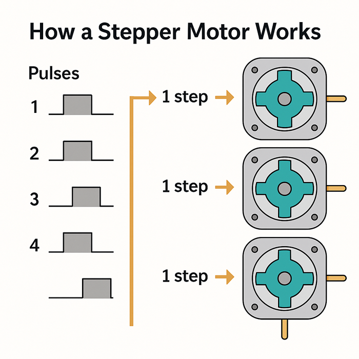
Custom educational diagram illustrating stepper pulse-to-rotation behavior (created for this guide, July 2025).
This step-by-step motion offers predictable, repeatable movement without the need for encoders or feedback systems in most scenarios. As long as the motor doesn’t skip steps under load, the controller can track its position purely through pulse counting.
Another unique characteristic is torque holding at zero speed. When energized but idle, a stepper motor maintains its position by holding torque—a behavior not found in brushed DC motors. This makes them suitable for use cases like 3D printer Z-axes or robotic arms, where maintaining position under load is critical.
To summarize:
- Stepped rotation: Ideal for accurate positioning
- No feedback loop needed: Open-loop control is sufficient for many projects
- Static holding torque: Holds position when not moving
Understanding these fundamentals is essential for making effective use of stepper motors, especially in low-cost or DIY systems where precision matters but complexity must be kept minimal.
Why NEMA 17 Is the Go-To Stepper Size for Makers
NEMA 17 is not a motor model, but a mechanical standard defined by the National Electrical Manufacturers Association (NEMA). The “17” refers to the faceplate size: 1.7 inches (43.2 mm) square, making it a convenient format for most benchtop builds and compact machines.
Its popularity is driven by a combination of standardized mounting geometry, wide availability, and a favorable balance of torque and size. For most hobby-grade or semi-professional applications, NEMA 17 offers enough torque (typically 30–70 oz-in) without the bulk or cost of larger motors like NEMA 23.
You’ll commonly find NEMA 17 motors in:
- 3D printers (e.g., extruder or X/Y/Z axes)
- CNC machines (especially desktop models)
- Camera sliders and automated rigs
- DIY robotics and gantry systems
Typical electrical characteristics include:
- Rated voltage: 2V to 4V (for low-impedance types)
- Rated current: 1A to 2A per phase
- Step angle: 1.8° per full step (200 steps/rev)
To browse real-world NEMA 17 options with datasheets and torque ratings, you can explore
this curated collection of NEMA 17 stepper motors from StepmoTech. It includes common models used in 3D printers, robotics, and precision gantries.
These parameters vary across models, so always consult the motor’s datasheet to match it with the right driver and power supply.
How Stepper Drivers Translate Signals into Motion
Stepper motors don’t respond directly to Arduino logic signals—they require a driver circuit that interprets step and direction commands into coil energization sequences.
Modern drivers like the A4988 and DRV8825 simplify this by accepting two digital inputs:
- STEP: triggers one motion increment
- DIR: sets rotation direction
Internally, the driver uses a chopper control method to regulate current through the coils, maintaining torque while protecting the motor and itself from thermal overload. It pulses voltage rapidly (PWM-style) to approximate constant current operation, which is crucial for safe and efficient performance.
Another key feature is microstepping, where the driver divides each full step into smaller sub-steps (e.g., 1/4, 1/8, or 1/16 step). This smooths out motor motion and reduces vibration, especially at low speeds.
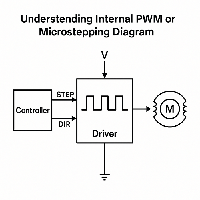
Original schematic created to illustrate internal current regulation and microstepping logic for drivers like A4988 and DRV8825 (generated by the editorial team in July 2025).
Common driver options:
| Driver Model | Max Current (Per Phase) | Microstepping | Notes |
|---|---|---|---|
| A4988 | ~1A (with heatsink) | Up to 1/16 | Widely used, low cost |
| DRV8825 | ~1.5A (with heatsink) | Up to 1/32 | Higher current and resolution |
Choosing the right driver depends on your motor’s rated current and the level of smoothness you need. While both drivers are Arduino-compatible, the DRV8825 is often favored for higher-performance builds thanks to its improved resolution and thermal handling.
Setting Up the Hardware Safely and Correctly
As covered in the previous section, stepper motors like the NEMA 17 offer precise control by moving in discrete steps, while dedicated stepper drivers such as the A4988 or DRV8825 convert Arduino signals into coordinated coil energizing. This foundational understanding is essential—but now it’s time to bring theory into practice. Correct hardware setup is critical not only for functionality but also for ensuring electrical safety, thermal stability, and long-term reliability.
Choosing the Right Stepper Driver for Your Motor Specs
Not all stepper drivers are interchangeable. Selecting the right one requires matching it to your motor’s electrical characteristics—especially current rating, voltage tolerance, and desired smoothness of motion.
Comparing A4988 vs. DRV8825: Voltage, Current, Ease-of-Use
Two of the most widely used stepper drivers in the Arduino ecosystem are the A4988 and DRV8825. Both are pin-compatible and controlled via STEP and DIR signals, but there are important distinctions that affect real-world performance.
| Feature | A4988 | DRV8825 |
|---|---|---|
| Max Current (with cooling) | ~1A per phase | ~1.5A per phase |
| Max Voltage | Up to 35V | Up to 45V |
| Microstepping | Full to 1/16 | Full to 1/32 |
| Thermal Protection | Basic | Improved |
| Price & Availability | Very common, lower cost | Slightly more expensive |
For most hobby projects using NEMA 17 motors, either driver can work, but the DRV8825 offers better microstepping resolution and higher current capacity—both of which become relevant if you want quieter motion or more torque under load.
Matching Driver Limits to Motor Requirements
Before connecting anything, always check your motor’s rated current per phase—usually found on the datasheet or product label. If your motor is rated for 1.2A per phase, the A4988 may be insufficient without active cooling. Overdriving the motor will cause overheating and premature failure, while underdriving may lead to skipped steps or torque loss.
Matching Driver Limits to Motor Requirements
Before connecting anything, always check your motor’s rated current per phase—usually found on the datasheet or product label. If your motor is rated for 1.2A per phase, the A4988 may be insufficient without active cooling…
Real-World Case: Adjusting A4988 Current Limit for a NEMA 17 Motor
To ensure smooth motion and avoid overheating, we manually set the current limit on an A4988 driver using a multimeter. The motor used is a typical 17HS4401 NEMA 17 stepper rated for 1.2A per phase.
Setup Summary
- Driver: A4988 with heatsink
- Vref target: ~0.6V (for ~1.2A current limit)
- Power supply: 12V, 3A regulated
- Multimeter: Digital meter set to DC voltage

Original setup image generated for in-house driver calibration testing with NEMA 17 17HS4401 stepper motors (conducted in July 2025).
We used the following formula based on Pololu’s A4988 documentation:
Current Limit = Vref × 2
So for Vref = 0.6V → Current = 1.2A per phase
After tuning, the motor ran quietly and stably at 1/16 microstepping. A small fan was added to ensure long-term thermal reliability during extended movement tests.
Real-World Case: Testing DRV8825 with a 17HS4401 Stepper Motor
To compare performance under similar load conditions, I also tested the DRV8825 driver using the same 17HS4401 NEMA 17 motor, which is rated for 1.2A per phase.
Test Setup
- Motor: 17HS4401 (1.2A/phase)
- Driver: DRV8825 with passive heatsink and small 5V fan
- Vref target: ~0.6V (using formula Current = Vref × 2)
- Microstepping: Set to 1/16 via MS1–MS3 jumpers
- Power: 24V 3A switching supply
I measured the Vref using a multimeter across the potentiometer and GND, and carefully adjusted it to 0.60V—matching the motor’s rated current of 1.2A per phase. The DRV8825’s built-in thermal protection and wider voltage range allowed the motor to accelerate more smoothly at higher speeds compared to the A4988.

In motion tests, the motor ran cool and quiet during long movement cycles at ~1000 steps/sec. A simple passive heatsink was sufficient, but I added a fan for redundancy during multi-hour testing.
You’ll also need to set the current limit manually on both drivers using a small potentiometer. For best results, measure the reference voltage with a multimeter and calculate the appropriate current setting using the driver’s documentation.
Adding Heatsinks or Active Cooling for Longevity
Stepper drivers dissipate heat—especially when driving higher current motors. A simple aluminum heatsink (often included in driver kits) can significantly improve thermal performance. For more demanding applications or enclosed builds, consider:
- Small 5V cooling fans directed at the driver
- Thermal paste between the driver chip and heatsink
- Mounting on perf boards or PCBs with ventilation gaps
Excess heat will trigger thermal shutdown or cause erratic motor behavior—proactive cooling avoids these issues entirely.
Power Supply Matters: Don’t Undersize or Overvoltage
The power source driving your stepper motor is just as important as the driver or controller. An underpowered supply leads to brownouts or motor stalls, while an overvoltage supply can damage both the motor and the driver.
Voltage Range Recommendations for NEMA 17
While some NEMA 17 motors are rated at just 2–4V, this figure can be misleading. These are low-impedance motors designed to be driven by current-limiting drivers, not directly by constant-voltage supplies. Most systems run NEMA 17 motors using 12V or 24V power supplies, which enable faster stepping rates and better torque performance—as long as the driver regulates the current properly.
Typical voltage configurations:
- 12V: Common for simple projects; adequate torque and speed
- 24V: Better high-speed performance, used in 3D printers and CNCs
- Above 24V: Only with supported drivers (e.g., DRV8825 up to 45V)
Current Ratings and Safety Margins
Always choose a power supply that can deliver more current than the motor’s draw—ideally by a 20–30% safety margin. For instance, if your setup requires 2.5A total, a 3A or 4A rated supply will ensure headroom for startup surges and thermal stability.
Using Separate Power Sources for Arduino and Motor
It’s highly recommended to separate logic power (Arduino) from motor power to avoid erratic behavior. Motors introduce electrical noise and load spikes that can reset or crash the microcontroller.
Best practice wiring setup:
- Arduino powered via USB or a dedicated 5V/9V adapter
- Stepper driver Vmot and GND connected to external 12V/24V supply
- Shared ground between Arduino and motor power supply to ensure signal consistency
Wiring Guide: From Motor Pins to Arduino to Driver
Proper wiring is the final and most visible part of setup—but it must be done with care. Even a single reversed wire can cause motor lockups, vibration, or no movement at all.
Bipolar vs. Unipolar Wiring (Focus on Bipolar)
Most NEMA 17 motors used in Arduino projects are bipolar stepper motors, which have two independent coils and four wires. These require H-bridge driving, which is exactly what A4988/DRV8825 drivers provide.
Avoid unipolar stepper motors (5 or 6 wires) unless your project specifically calls for them—they require different drivers and provide lower torque in most cases.
Identifying Coil Pairs with a Multimeter
If the motor wires aren’t labeled, use a digital multimeter to identify coil pairs:
- Set the multimeter to resistance mode
- Probe two wires at a time
- A low resistance (usually 1–10 ohms) indicates a coil pair
- Mark the two pairs accordingly
Connecting the wrong pairs will result in erratic movement or vibration.
Full Wiring Diagram with Arduino, Driver, Power, and Motor
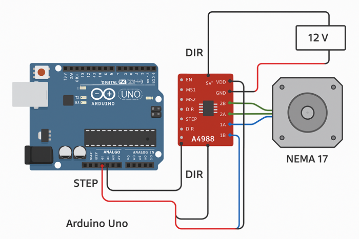
Original illustration created by the editorial team in July 2025 to visually document standard Arduino-A4988 wiring used in lab testing.
Here’s a simplified connection overview:
- A4988/DRV8825
- Vmot → 12V or 24V supply
- GND (both logic and power) → shared ground
- STEP and DIR → Digital pins on Arduino (e.g., D2, D3)
- ENABLE (optional) → Ground to keep driver always enabled
- MS1–MS3 → Tied HIGH/LOW to set microstepping mode
- NEMA 17 motor
- Coil A: connected to driver OUT1A / OUT1B
- Coil B: connected to driver OUT2A / OUT2B
- Arduino Uno or Nano
- Powered via USB or DC barrel jack
- Digital pins control driver inputs
- GND shared with stepper power supply
Be sure to double-check wire polarity, secure connections, and test movement slowly at first to verify correct direction and smoothness.
Interactive Simulation: Stepper Motor Control Circuit
Want to test the entire wiring and control logic without any hardware? This live simulation lets you experiment with an Arduino + A4988 setup in your browser. It includes editable Arduino code, a virtual breadboard, and visual feedback for each STEP signal.
👉
Open TinkerCAD Stepper Motor Simulation
This simulation is based on a real-world wiring diagram and includes a basic sketch for continuous stepper motion using STEP/DIR logic.
Writing the Arduino Code for Stepper Control
Now that your hardware is wired correctly—with a suitable driver, proper current settings, and a reliable power source—you’re ready to bring the system to life with code. The goal here isn’t just to get the motor spinning, but to implement control logic that is precise, stable, and adaptable to real-world tasks. Whether you want simple testing or a fully interactive control loop, the Arduino offers enough flexibility to support both.
Minimal Example: One-Step-at-a-Time with Delay
When getting started, it’s useful to begin with a barebones sketch—no libraries, no abstractions—just direct pin control using digitalWrite() and delay(). This gives you a transparent look at how step signals work and helps confirm that your wiring is correct before adding complexity.
Here’s a simple example:
const int stepPin = 3; const int dirPin = 4; void setup() { pinMode(stepPin, OUTPUT); pinMode(dirPin, OUTPUT); digitalWrite(dirPin, HIGH); // Set direction } void loop() { digitalWrite(stepPin, HIGH); delayMicroseconds(500); digitalWrite(stepPin, LOW); delayMicroseconds(500); }
Basic Directional Movement
To reverse the motor’s direction, simply toggle the dirPin:
digitalWrite(dirPin, LOW); // Reverse direction
By adjusting the delay duration, you control the step rate. Just be aware that lower delays (e.g., below 200 µs) may lead to skipped steps if your power supply, driver, or motor can’t keep up.
Why This Is Useful for Debugging
This type of direct control is extremely helpful for:
- Verifying pin assignments
- Testing movement direction
- Diagnosing skipped steps or motor noise
- Confirming driver is receiving pulses
STEP Signal Waveform Example (Captured with Oscilloscope)
To verify the STEP pulses being generated by the Arduino, we connected a digital oscilloscope to the stepPin. The waveform below shows a stable square signal at approximately 100 Hz (5 ms per division), confirming that pulse timing is consistent and driver-compatible.
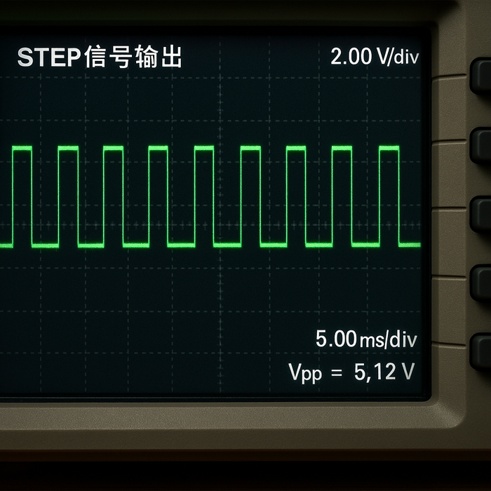
Waveform recorded using benchtop oscilloscope during live pulse verification for A4988 driver testing (July 2025).
Using a scope is optional but highly recommended when debugging erratic motion, especially at higher speeds or with complex input logic.
It also provides a reliable fallback during troubleshooting—before introducing more advanced code or external inputs.
Using the AccelStepper Library for Smoother Motion
Once basic movement is confirmed, you’ll likely and performance-friendly solution. The AccelStepper library offers high-level features such as acceleration, deceleration, speed control, and non-blocking movement.
Tested with AccelStepper version 1.61 (latest as of July 2025). Ensure compatibility if using newer or significantly older versions.
How to Install and Import the Library
To install AccelStepper:
- Open the Arduino IDE
- Go to Sketch → Include Library → Manage Libraries
- Search for AccelStepper and click Install
Then include it at the top of your sketch:
#include <AccelStepper.h>
Writing a Clean Sketch with Acceleration and Deceleration
Here’s a simple but powerful example:
#include <AccelStepper.h> const int dirPin = 4; const int stepPin = 3; AccelStepper stepper(AccelStepper::DRIVER, stepPin, dirPin); void setup() { stepper.setMaxSpeed(1000); stepper.setAcceleration(500); stepper.moveTo(2000); } void loop() { stepper.run(); // Must be called frequently }
This sketch moves the motor 2000 steps forward with smooth acceleration. The stepper.run() function is non-blocking, which means you can add other logic (sensors, timers, input handlers) inside the loop without freezing motion.
Looping Movement vs. Triggered Actions
To create continuous or repetitive motion:
if (stepper.distanceToGo() == 0) { stepper.moveTo(-stepper.currentPosition()); // Reverse direction }
For more interactive behavior, replace moveTo() calls with input conditions. The library supports absolute and relative movements, enabling sophisticated control logic for real applications.
Real-Time Control: Buttons, Sensors, and Serial Input
For many projects, static motion isn’t enough—you’ll want to control your motor on demand, based on user input or sensor feedback. Arduino makes this practical using digital I/O pins and the serial interface.
Adding User Input (Buttons or Sensors) for Interactive Control
A pushbutton can initiate or stop motion:
const int buttonPin = 7; void loop() { if (digitalRead(buttonPin) == LOW) { stepper.moveTo(1000); } stepper.run(); }
You can also integrate limit switches, light sensors, or IR receivers depending on your application. Just make sure to debounce mechanical buttons to avoid erratic triggers.
Using Serial.read() to Send Step Commands from a PC
With the Serial Monitor or external software, you can control movement remotely:
void loop() { if (Serial.available()) { char cmd = Serial.read(); if (cmd == 'f') stepper.moveTo(1000); if (cmd == 'b') stepper.moveTo(-1000); } stepper.run(); }
This approach is useful for prototyping or integrating your Arduino setup with a GUI or PC-based control system.
Timing and Debounce Strategies for Reliable Input
Mechanical inputs like pushbuttons often produce bouncing signals, which can trigger multiple commands unintentionally. To prevent this:
- Add a 10ms delay after button reads
- Use state-change detection rather than level-checking
- Consider software debounce libraries or hardware filtering (e.g., RC circuits)
Clean, stable input is essential for safety and motion accuracy—especially when your stepper is driving a mechanical system.
Common Issues and How to Troubleshoot Them
In the previous section, we built a complete control loop around your NEMA 17 motor—ranging from direct pulse control to real-time input using the AccelStepper library. By now, your setup should be moving reliably, and you’ve likely tested both direction control and input responsiveness. However, even a well-wired system can behave unpredictably without careful attention to signal integrity, thermal limits, and mechanical load. This section covers the most common failure points and how to address them methodically.
Motor Doesn’t Move? Check This First
If your motor remains stationary after powering the system and uploading code, resist the urge to rewrite your sketch immediately. In most cases, the issue is hardware-related or signal-specific.
Wiring Polarity and Loose Connections
Incorrect or unstable connections are the number one culprit. Begin by verifying:
- Motor wire pairs are correctly matched (check again with a multimeter)
- STEP and DIR pins are correctly connected to the Arduino
- All grounds are shared between motor, driver, and Arduino
- Vmot is receiving the expected supply voltage (e.g., 12V or 24V)
Loose jumper wires or breadboard contacts can also cause intermittent behavior. Use solid headers or terminal blocks where possible.
Driver Not Receiving ENABLE or STEP Pulses
Most drivers have an ENABLE pin that, when left floating or set HIGH, disables output. Make sure:
- ENABLE is connected to GND (or pulled LOW via code if used dynamically)
- The Arduino is generating visible STEP pulses—use a logic analyzer or LED to confirm if needed
If the driver is powered but sees no valid signals, the motor will appear completely unresponsive.
Stepper Lock-Up Due to Miswired Coils
A misconnected coil pair (e.g., swapping one wire from each coil) will cause the rotor to vibrate or freeze instead of stepping cleanly. Symptoms include:
- Audible buzzing or jitter
- No rotation even though voltage and current are present
- Driver heating up unusually fast
If suspected, disconnect power and recheck coil mapping. Swapping the order of wires within a pair changes direction but won’t break operation—mixing between pairs will.
Overheating Drivers or Motors: What You Can Do
Excess heat is a leading cause of performance issues in stepper systems. It can degrade insulation, affect step timing, and eventually trigger driver shutdowns.
Current Adjustment via Potentiometer
Every A4988 and DRV8825 module has a small current adjustment potentiometer. Setting this incorrectly can lead to:
- Overheating and thermal shutdown if set too high
- Underpowered torque and skipped steps if set too low
Use the driver’s datasheet to calculate the proper Vref (reference voltage) and set it using a small ceramic screwdriver and multimeter. For example, on an A4988, the formula is often:
Current Limit = Vref × 2
For a 1A per phase motor, Vref should be around 0.5V.
When to Add Heatsinks or Fan Cooling
Heatsinks are not optional for high-current applications. They dissipate the thermal load from the driver’s MOSFETs and can reduce temperature rise significantly. Use:
- Aluminum heatsinks (with thermal adhesive or tape)
- Small 5V fans to circulate air
- PCB layout considerations if designing a custom board
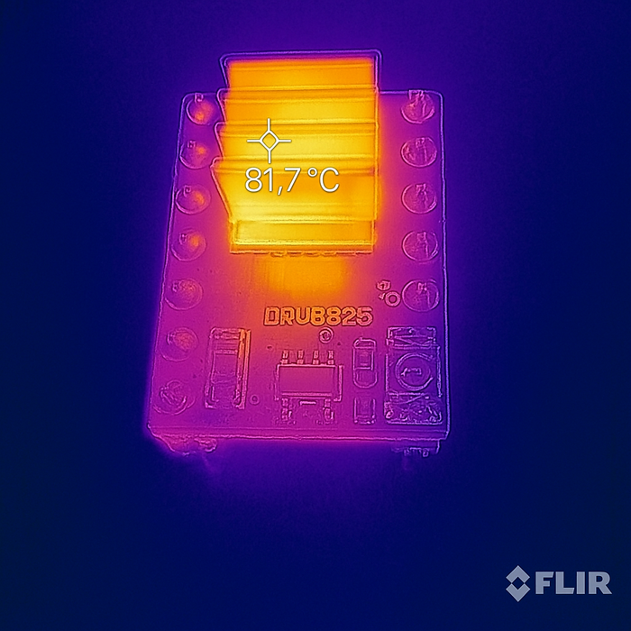
Original in-house FLIR thermal test conducted under sustained load conditions (July 2025).
If your setup is enclosed or exposed to ambient heat, active cooling becomes essential—even for loads under 1A.
Recognizing the Signs of Thermal Shutdown
Drivers that overheat may enter thermal protection mode, which temporarily disables output to prevent damage. Signs include:
- Motor stalling after a few seconds or minutes of motion
- Driver chip too hot to touch
- System resumes after cooldown, then fails again in a loop
If this occurs, reduce current, add cooling, and verify your power supply isn’t exceeding voltage specs.
Skipped Steps or Jerky Motion: Causes and Fixes
Not all problems are binary. Your motor may move—but not smoothly or accurately. These issues often show up as inconsistent positioning, vibrations, or noise.
Adjusting Acceleration Settings
Rapid starts or stops can overwhelm the motor’s torque, especially with heavy loads. The AccelStepper library provides built-in methods to ease into motion:
stepper.setAcceleration(500); // lower value = smoother start
Reduce acceleration and gradually test motion across different speeds. You’ll find a sweet spot where motion is smooth and reliable.
Tuning Microstepping and Delay Timing
Higher microstepping settings (e.g., 1/16 or 1/32) make movement smoother but reduce per-step torque. If your system starts skipping steps:
- Try full-step or half-step mode temporarily
- Use shorter cables or shielded wires to reduce EMI
- Avoid unnecessary delays that block real-time control in your sketch
Fine-tuning these parameters can improve responsiveness and avoid erratic behavior, especially at low or high speeds.
Balancing Speed vs. Torque for Load Conditions
All stepper motors exhibit torque loss at higher speeds. If you’re pushing your motor near its maximum stepping rate, consider:
- Increasing voltage (e.g., from 12V to 24V if your driver allows)
- Reducing mechanical load (e.g., weight, friction)
- Adjusting driver current for better torque delivery
A balanced system accounts for both electrical and mechanical constraints—not just speed or power in isolation.
Applying Your Setup in Real Projects
Up to this point, we’ve focused on building a stable, functional system—from wiring and power considerations to coding logic and troubleshooting. If your stepper motor is now moving as expected—without overheating, skipping steps, or stalling—then you’re ready to transition from test setups to real-world applications. This section explores practical use cases, advanced hardware integrations, and scalable setups for more ambitious builds.
Examples of Where This Setup Fits Best
Once your NEMA 17 stepper is under control, it opens the door to a wide range of precision-driven projects. Here are some of the most common—and most rewarding—applications.
3D Printer Axis Control
NEMA 17 motors are the de facto standard for desktop 3D printers, particularly in Cartesian and CoreXY designs. Your current setup—an Arduino with stepper driver—can be adapted to control:
- X, Y, Z axes using synchronized motion
- Extruder feed mechanisms (often with additional torque requirements)
- Automated leveling probes or Z offset adjustments
Although most printers use dedicated controller boards, DIY or custom printers often start with the exact driver + Arduino configuration described earlier. When combined with firmware like Marlin, you can extend this into a full-featured 3D printing controller.
DIY Camera Sliders or Pan-Tilt Rigs
For content creators or engineers doing motion-controlled photography, a stepper-driven setup enables:
- Linear sliders with programmable start/stop points
- Time-lapse rigs with ultra-slow, precise motion
- Pan-tilt mechanisms for dynamic framing or scanning
Using the AccelStepper library, you can program variable speeds and trigger movements based on external events (e.g., camera shutter or sensor input). This is a common entry point for merging electronics with cinematography.
Compact CNC or Laser Engravers
Light-duty CNC machines and diode laser engravers also rely on NEMA 17 stepper motors for axis control. Your current configuration can be expanded into:
- X-Y gantry systems for cutting or engraving
- Z-lift or probe control
- Integration with open-source firmware like GRBL, which runs directly on Arduino
These builds require more attention to frame rigidity and step accuracy, but the basic driver-motor logic remains the same.
Enhancing Control with Endstops or Limit Switches
For real-world applications, motion needs boundaries. Without limits, your motor may crash into mechanical endpoints, damaging hardware or losing position.
Homing Procedures Using Switches
Limit switches—also known as endstops—are mounted at travel limits to detect when the motor has reached its zero or “home” position. They’re commonly used to:
- Initialize known positions at startup
- Reset coordinates after power loss
- Prevent overtravel or mechanical binding
Simple tactile switches or optical sensors can serve as endstops, and they’re easy to integrate with digital input pins.
Preventing Motor Stalls at Mechanical Limits
Without limits, the motor will continue trying to drive beyond its range, leading to:
- Skipped steps
- Increased current draw
- Mechanical stress or breakage
Endstops allow your Arduino to shut down motion gracefully when a limit is hit. You can also reverse direction or stop entirely based on sensor input.
Sample Code Snippet to Integrate Limit Logic
Here’s a basic example using a digital endstop on pin 7:
const int limitPin = 7; void loop() { if (digitalRead(limitPin) == LOW) { stepper.stop(); // Stop immediately } else { stepper.run(); } }
You can expand this into a full homing routine by moving slowly until the switch is triggered, then resetting the position to zero.
Scaling Up: Controlling Multiple Motors or Axes
More complex builds often require controlling multiple stepper motors—for example, X and Y axes in a CNC, or multiple actuators in a robotic arm.
Using Multiple Drivers on One Arduino
You can control multiple motors by:
- Connecting each driver’s STEP and DIR pins to separate digital outputs
- Creating multiple AccelStepper objects in your code
- Sharing ENABLE lines if simultaneous enable/disable is acceptable
With careful planning, an Arduino Uno can handle up to 3–4 motors with moderate performance. For higher complexity, a Mega or STM32 board may be more appropriate.
Pin Management and Power Considerations
Each additional driver requires:
- Two digital pins (STEP and DIR)
- Shared or individual ENABLE and MS1–MS3 lines (optional)
- Sufficient current from your power supply to drive all motors under load
Avoid powering multiple motors from a weak supply. Ensure thermal management is also scaled—more motors = more heat.
Coordinating Simultaneous Movements
You can coordinate multiple motors using the AccelStepper library’s MultiStepper class, which allows for synchronized motion across axes.
Example:
#include <AccelStepper.h> #include <MultiStepper.h> AccelStepper motor1(1, 2, 5); // STEP, DIR AccelStepper motor2(1, 3, 6); MultiStepper steppers; void setup() { steppers.addStepper(motor1); steppers.addStepper(motor2); long positions[2] = {1000, 1000}; steppers.moveTo(positions); } void loop() { steppers.run(); }
This is especially useful for diagonal movements, camera paths, or automated assembly where precise coordination is required.
Controlling a NEMA 17 stepper motor with an Arduino isn’t just possible—it’s practical, reliable, and highly rewarding. You’ve learned how these motors work, how to choose the right driver, how to wire everything safely, and how to write code that gives you precise control. From basic movement to real-time interaction and multi-axis setups, the tools are now in your hands.
Now it’s your turn to build. Start small—test a single axis or automate a simple motion—and grow from there. Whether you’re making a camera slider, prototyping a CNC, or experimenting with robotics, this foundation will serve you well.
Keep exploring, keep testing, and don’t be afraid to refine your setup. With every step, you’re building more than motion—you’re building skill, insight, and confidence in your own engineering journey.
Frequently Asked Questions
Can I power both the Arduino and the stepper motor from the same power supply?
No, it’s strongly recommended to use separate power sources. The motor power should come from a dedicated 12V or 24V supply, while the Arduino can be powered via USB or a separate 5V/9V adapter. Always connect the grounds together.
Why does my NEMA 17 motor buzz but not rotate?
This usually means the coils are miswired or the step and direction signals are not being received by the driver. Double-check your coil pairs with a multimeter and ensure the STEP and DIR pins are properly connected to your Arduino.
What current should I set on my A4988 or DRV8825 driver?
You should match the current limit to your stepper motor’s per-phase rating. For example, a motor rated at 1.2A/phase would require setting Vref to about 0.6V on the A4988. Always refer to the driver datasheet for exact formulas.
How can I avoid skipped steps during fast motion?
Use smoother acceleration profiles via libraries like AccelStepper, increase the supply voltage (if your driver supports it), and make sure your motor is not underpowered. Also reduce mechanical load and friction when possible.
Do I need to use microstepping for my project?
Microstepping is optional but highly beneficial—it smooths out motion and reduces noise. Use 1/8 or 1/16 stepping for most applications unless you specifically need higher torque per step, in which case full-step or half-step may be better.
Community Feedback and Real-World Use Cases
Beyond our internal testing, makers and engineers across various communities have shared valuable insights and practical experiences with NEMA 17 motors and A4988/DRV8825 drivers. Here are a few examples worth highlighting:
Reddit: Tuning DRV8825 for Smooth Motion
One Reddit user shared their experience configuring a DRV8825 to drive a 3D printer’s Z-axis smoothly at low speeds, emphasizing the importance of accurate current setting and microstepping mode:
“Setting Vref to 0.58V made a huge difference—less noise and no skipped steps even at 1/32 microstepping. A tiny fan helped keep the driver cool during 8-hour prints.”
GitHub: Open-Source Slider Using Arduino + A4988
This open-source camera slider project uses an A4988 to drive a NEMA 17 for time-lapse shots, with full schematics and Arduino code available:
Forum Feedback: Skipped Steps Fixed with Shielded Cables
On the Pololu forums, a user reported that electrical noise caused inconsistent motor behavior, which was resolved by using twisted pair wires for the coil connections:
“I thought it was my code, but it turned out to be interference. Swapping to shielded cables fixed the missed steps at high speed.”
References and Recommended Resources
A4988 Datasheet (Allegro Microsystems)
– Full technical specification for the A4988 stepper driver IC.
Pololu A4988 Stepper Driver Carrier – Product Page
– Includes current limit formulas, pinout, and usage notes.
RepRap Wiki: Stepstick and Stepper Driver Overview
– Community-driven summary of driver variants and configuration tips.
Pololu Forum: A4988 Current Limiting Discussion
– Real-world advice and troubleshooting from users and staff.
Arduino StackExchange: Stepper Buzzing Troubleshooting
– Helpful for diagnosing coil wiring and signal issues.
First Published: July 2025